From Pixels to Tensors, Part 1: 2D Rendering Baselines
June 07, 2026 [hardware-architecture] #2d-rendering #nes-ppu #font-rasterization #linux-drm #x11 #pixels-to-tensorsI started this series because I wanted to understand how ML compiler stacks built on MLIR actually work — not just the API surface, but why they are shaped the way they are. The trail goes back to GPU architecture, to the 3D pipeline, to the fixed-function hardware that preceded it.
This is that backward journey. It starts at 2D rendering — font rasterization, geometry primitives, the NES PPU — because that is where per-pixel parallelism first became a hardware design constraint. Every abstraction in modern GPU programming, and eventually in MLIR's compilation model, is a response to problems that showed up here first.
The series runs: 2D rendering → 3D GPU pipeline → GPGPU → deep learning → MLIR.
This series of articles represents my own attempt to understand the technical evolution from pixels to tensors. Each domain along this path—graphics, hardware architecture, compilers, and machine learning—is an extraordinarily deep field. I cannot claim to have fully mastered any of them. I am simply tracing this intellectual thread through first-principles reasoning and historical inquiry, documenting the process as I go. I hope these notes, however incomplete, may offer some value to fellow explorers navigating the same topics.
2D Rendering
2D Rendering Baselines: Font Rasterization
The rendering pipeline converts character streams (ASCII, Unicode) into pixel bitmaps. Two encoding formats determine the conversion mechanism:
- Bitmap fonts: each character is stored as a fixed grid of pixels. Fast to draw, but looks blurry when scaled.
- Vector fonts (TrueType
.ttf/ OpenType.otf): each character is stored as a set of curves (Bézier curves). The renderer rasterizes them at whatever size is needed. This is what every modern OS uses.
When entering a character in a terminal, the pipeline looks roughly like this:
Keypress
    │
    ▼
Character code (e.g. ASCII 'A' = 65)
    │
    ▼
Font engine (FreeType, Core Text...)
  → looks up the glyph outline from the .ttf file
  → rasterizes it into a glyph bitmap in temporary memory
    │
    ▼
Application composites glyph bitmap into framebuffer
  → CPU copies pixel values from glyph bitmap to the correct
    position in the framebuffer (with alpha blending if needed)
    │
    ▼
Framebuffer (memory-mapped display memory)
  → CPU writes pixel values directly to this memory region
    │
    ▼
Display controller
  → reads framebuffer 60 times per second
  → sends pixel data line by line to the monitor (scanline output)
    │
    ▼
Monitor
The set-face-attribute call writes font properties into a Lisp_String's interval tree — the display engine reads those intervals back out and feeds them into the same FreeType rasterization path. (Emacs Internal #04: Interval Trees)
How a Software-Rendered Terminal Talks to the Display Hardware
"Drawing to the screen" is not one system call — it is a sequence of calls to the Linux DRM (Direct Rendering Manager) subsystem, with the actual pixel writing happening without any system call at all.
The terminal bypasses the display server entirely, talking directly to the kernel's DRM subsystem.
Step 1 — Open the device
In Linux, everything is a file. The GPU and display controller are exposed as device files:
int fd = open("/dev/dri/card0", O_RDWR);Step 2 — Allocate a Dumb Buffer
The display controller needs physically contiguous, aligned memory — not just any malloc'd region. The application asks the DRM kernel subsystem for it via ioctl:
ioctl(fd, DRM_IOCTL_MODE_CREATE_DUMB, &args);
// args: width=1920, height=1080, bpp=32
// returns: a handle to the allocated buffer
Step 3 — Map the buffer into user space
Making a system call per pixel would be impossibly slow. Instead, the application maps the display memory directly into its own virtual address space:
ioctl(fd, DRM_IOCTL_MODE_MAP_DUMB, &args); // returns a fake offset for mmap
void *fb = mmap(NULL, size, PROT_READ|PROT_WRITE, MAP_SHARED, fd, offset);
The offset is not a real file offset. It is an opaque cookie from the DRM subsystem that mmap uses to wire the virtual memory range to the underlying physical framebuffer.
Now fb is just a regular C pointer. Writing to it writes directly to display memory.
Step 4 — Draw (no system call)
Once mmap is done, the application is in complete control. FreeType rasterizes each glyph into a temporary bitmap in user-space memory. The application then copies those pixels into fb at the correct (x, y) position — potentially with alpha blending for subpixel anti-aliasing. None of this involves the kernel. It is just CPU memory writes to a mapped buffer.
Step 5 — Tell the display controller to show it (Double Buffering)
If there were only one buffer, the display controller would be scanning it out while the CPU is still writing into it — producing screen tearing: the top half of the screen shows the old frame and the bottom half shows the new one, split at whatever scanline the controller happened to be on.
The fix is double buffering: two buffers that swap roles every frame.
Frame N:   CPU writes into Back Buffer
           Display controller scans out Front Buffer

Page Flip: swap the pointers (one ioctl, almost free)

Frame N+1: CPU writes into the old Front Buffer (now Back)
           Display controller scans out the old Back Buffer (now Front)
The flip is triggered during Vblank — the vertical blanking interval between frames when the display controller is not actively scanning out pixels — so the switch is invisible to the viewer.
ioctl(fd, DRM_IOCTL_MODE_ADDFB, &fb_args);   // register the buffer
ioctl(fd, DRM_IOCTL_MODE_PAGE_FLIP, &flip);  // flip at next Vblank
Why Software Rendering Hits a Wall at 4K 60fps
At 640×480 this pipeline works. At 4K 60fps, it doesn't — the numbers show why.
Assumptions:
- Resolution: 3840 × 2160 (4K UHD)
- Bytes per pixel: 4 (32-bit RGBA)
- Refresh rate: 60 Hz
Step 1 — Pixels per frame
\[3840 \times 2160 = 8,\!294,\!400 \text{ pixels}\]
Step 2 — Bytes per frame
\[8,\!294,\!400 \times 4 \text{ bytes} = 33,\!177,\!600 \text{ bytes} \approx 33.18 \text{ MB}\]
Step 3 — Bandwidth for a full-screen write every frame
\[33.18 \text{ MB} \times 60 = 1,\!990.7 \text{ MB/s} \approx 1.99 \text{ GB/s}\]
That is just for one memcpy per frame. In a real software compositor:
- Alpha blending requires read-modify-write: read the existing pixel, blend, write back. That doubles the bandwidth to ≈ 4 GB/s.
- Scrolling, window movement, and overlapping windows add more passes.
Step 4 — The memory wall
A single channel of DDR4-3200 has a theoretical peak of 25.6 GB/s. In practice, achievable throughput is far lower, and the CPU is competing with every other process for that bandwidth. A 4 GB/s framebuffer copy alone consumes a significant fraction of available memory bandwidth, leaving little room for the actual application logic.
No modern desktop compositor does this. Instead, it uses the GPU's 3D pipeline.
2D Rendering Baselines: Geometry Rasterization
X11 draws with five primitives:
DrawPoint— single pixelDrawLine— Bresenham line algorithmDrawRectangle— axis-aligned rectangle fillFillPolygon— scanline polygon fillDrawArc— arc and ellipse drawing
X11 composites these primitives layer by layer, back to front — each new layer overwrites pixels from layers below it:
Application (X11 client)
    │
    ▼
Widget Tree Traversal (back to front, z-order)
    │
    ▼
Per-Widget Draw Call
    │
    ├── DrawRectangle (background fill)
    ├── DrawText → Font Pipeline (glyph rasterization + composite)
    ├── DrawLine / DrawArc (border, separator)
    └── DrawPolygon (icon, custom shape)
    │
    ▼
Framebuffer (all layers composited, topmost pixel wins)
    │
    ▼
Display Controller → Monitor
Each primitive call is independent — DrawLine does not see DrawRectangle's output, and DrawRectangle does not wait for DrawArc.
Combining the Two Pipelines
Both pipelines write to the same framebuffer. A terminal or window manager runs them in sequence each frame:
                        Draw Frame
                            │
            ┌───────────────┴───────────────┐
            │                               │
            ▼                               ▼
     Font Pipeline                   Geometry Pipeline
(glyph → bitmap → fb)          (primitives → rasterize → fb)
            │                               │
            └───────────────┬───────────────┘
                            │
                            ▼
                      Framebuffer
                            │
                            ▼
                 Display Controller → Monitor
A compositor can replace the entire CPU pipeline with a single draw call per window: two textured triangles, GPU-sampled and blended in parallel.
2D Gaming: The Hardware That Drove 3D
The 2D pipelines above describe a workstation or desktop OS. Games introduced a different pressure: real-time interactive rendering at a fixed hardware budget, with no OS compositor in the way.
The NES (1985) is the clearest example of where that pressure leads. Nintendo's engineers had one goal — 60fps at the lowest possible cost — and the result was the PPU: a dedicated fixed-function compositor that handles everything the CPU cannot afford to do.
Super Mario Bros: How Side-Scrolling Works
Super Mario Bros (NES, 1985) is a 2D side-scrolling game. The display hardware — the NES PPU (Picture Processing Unit) — was designed around a fixed set of compositing rules, not a programmable pipeline.
Data Structures: Three Object Types
The game world is built from three distinct object types, each with its own data layout and update rule:
-
Map (static background) — the level layout is defined in PRG ROM as a grid of metatiles (16×16 pixel blocks) assembled from 8×8 tiles in the Pattern Table. The CPU streams this data into the PPU's Name Table (a 32×30 tile-index grid) and Attribute Table (palette selectors). The ROM data is static, but the Name Table is updated every frame as scrolling exposes new tiles at the edge of the viewport.
-
Mario (player character) — stored as a set of state variables in CPU RAM: position (x, y), velocity, animation frame, power-up status, and a reference to which tile indices represent his current pose. The CPU updates these variables based on controller input and physics every frame.
-
Enemies and moving objects — each enemy (Goomba, Koopa, etc.) is an entry in an object slot array, holding its own x/y position, velocity, animation frame, and active flag. The CPU processes all active objects each frame: applying gravity, checking collisions with the map and with Mario, and updating their OAM entries. Moving platforms, fireballs, and power-up items follow the same slot-based pattern.
The NES offloads all pixel output to a dedicated chip — the PPU (Ricoh 2C02) — because the Ricoh 2A03 CPU cannot sustain the memory bandwidth required for full-screen updates at 60fps. The map becomes Name Table entries, Mario and enemies become OAM slots, animation becomes a tile index change. The CPU updates state; the PPU outputs pixels.
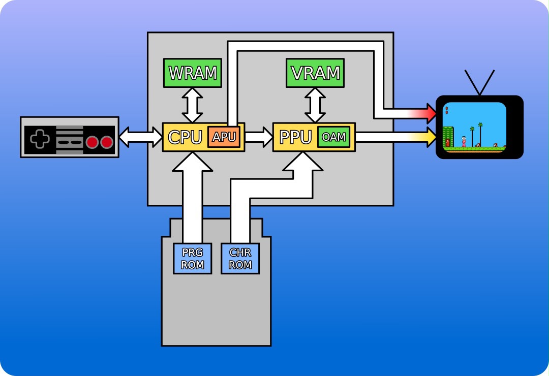
The CPU writes game state into WRAM and pushes tile/sprite data into the PPU's internal tables. The PPU reads those tables and streams pixels directly to the TV — one pixel per clock, no framebuffer.
The PPU has three hard constraints:
-
4 distinct memory regions that control the PPU: Pattern Tables (which hold the raw 8×8 pixel tile data), Name Tables (the background layout grid), Palettes (color definitions), and OAM (Object Attribute Memory for dynamic foreground sprites).
-
Only 4 colors per palette. Because each pixel is represented by a 2-bit value (0-3), the index `0` is hardcoded by the hardware to be transparent. This leaves only 3 visible colors per tile, forcing developers to be highly creative with palette swapping.
-
No frame buffer and no programmable pipeline. The PPU is a pure fixed-function hardware compositor that evaluates the static ROM data and dynamic OAM state on the fly, outputting the NTSC analog signal scanline by scanline at 60fps.
What the PPU Composites Per Frame
Layer 0: Background (Name Table + Pattern Table)
    │
    ▼
Layer 1: Sprites (OAM: Object Attribute Memory, max 64 sprites,
         max 8 per scanline)
    │
    ▼
Priority logic: sprite priority bit vs. background tile
    │
    ▼
Color lookup (Palette RAM, 4 palettes for background, 4 for sprites)
    │
    ▼
NTSC signal output (256×240 visible, output at 60fps)
The PPU does not draw arbitrary pixels. It composites named objects — background tiles and sprites — at fixed screen coordinates.
Scrolling: A Moving Viewport Over a Static Map
From the player's view, the world scrolls left as Mario runs right. In hardware, Mario's screen position stays near-constant — the PPU shifts a 256×240 viewport across a static tile grid via two scroll registers.
World Map (static, stored as Name Table + Attribute Table)
    ┌──────────────────────────────────────────────────────────┐
    │   ... ground tiles ... brick ... pipe ... ...            │
    │                                                          │
    │         ┌──────────┐                                     │
    │         │ 256×240  │  ← PPU output viewport              │
    │         │ viewport │     scroll_x = player_x - 128       │
    │         └──────────┘     (viewport follows Mario)        │
    │                                                          │
    └──────────────────────────────────────────────────────────┘

When Mario moves right, scroll_x increases. The PPU fetches new
tiles from the Name Table at the right edge of the viewport. Old
tiles on the left are discarded.
The PPU updates the scroll register once per frame during Vblank. The hardware handles tile fetching automatically — the CPU writes to the scroll register, and the PPU does the rest.
Sprite Drawing: Why Mario Flickers
Sprites are separate from the background. Each sprite is an 8×8 or 8×16 pixel tile with an (x, y) screen position, stored in OAM (Object Attribute Memory). The PPU reads OAM during rendering and composites sprites on top of the background.
The PPU has a hard limit: 8 sprites per scanline. If a 9th sprite appears on the same scanline, the PPU simply drops it. Game developers cycle sprite priority every frame to spread the dropout across different sprites, creating the characteristic NES flicker.
The OAM evaluation unit processes at most 8 entries per scanline before pixel output begins — a fixed silicon limit, not a software bug.1, 2
Animation: No Computation, Just Tile Swapping
Mario does not deform or rotate. His animation is a tile flip-book: the CPU updates the sprite's tile index in OAM each frame, pointing to a different 8×8 tile in the Pattern Table. The PPU draws whatever tile is referenced — no computation, no interpolation.
Frame 0: Mario idle → sprite tile index = 0x00
Frame 1: Mario idle → sprite tile index = 0x01
Frame 2: Mario idle → sprite tile index = 0x02
Frame 3: Mario idle → sprite tile index = 0x01 (loop back)

Pattern Table (8KB, stored in PPU VRAM):
  [0x00] ┌────┐  [0x01] ┌────┐  [0x02] ┌────┐
         │    │         │ /\ │         │  O │
         │ /\ │         │/__\│         │ /│\│
         │/__\│         ││  ││         │ / \│
         └────┘         └────┘         └────┘
NES games have no sprite rotation or scaling — the PPU has no multiplier, no matrix transform, no interpolation. It composites pre-drawn tiles at integer screen coordinates. That is the entire rendering model.
Conclusion
Font rasterization, geometry rasterization, and sprite compositing share one property: per-pixel independence. A TUI renderer, a side-scrolling game, or a window compositor all reduce to the same two operations — rasterize and composite — with no cross-pixel dependencies within a layer. The NES PPU executes this in fixed silicon at 60fps. Part 2 takes that same property and asks what happens when it is exposed as a programmable pipeline.
From Pixels to Tensors Series:
- Part 1: 2D Rendering Baselines
- Part 2: The 3D Graphics Pipeline
- Part 3: Symbolic AI
Footnotes